9.2.4. OBJEM

The tool automatically calculates the volume in a user-defined part of the model. In the first steps, the control of the tool is similar to area measurement. The user places points in the model, which are immediately triangulated into a reference 3D surface. The perimeter of the reference surface must not cross itself or the edge of the model.
After the right-clicking of the points, the volume calculation is performed. It is symbolized by an animation in the model and takes a few seconds. The volume of the space between the reference surface and the model surface is measured. The calculation is 2.5D, that is, if there are multiple collisions with the surface at any location [X,Y], only the location with the smallest Z coordinate is considered for the calculation. For example, overhangs or pipes running above ground are ignored. During the calculation, the space is imaginary filled with small blocks. The result is the sum of their volumes. The spaces below the reference surface (excavation) and above it (excavation) are shown separately in the results.
The plotting of points is described in detail in the parent chapter 9.2.
The volume measurement uses the coordinate measurement function 9.2.1, distance 9.2.2 and area 9.2.3.
The export of coordinates and measurement results is described in chapter 9.3.
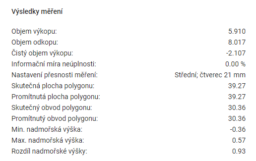
MEASUREMENT RESULTS
The Measurement Results table shows the summary data calculated for the measurements.
-
Excavation volume = the volume of the 3D model above the reference surface.
-
Dig volume = the volume of the 3D model under the reference surface.
-
Clean excavation volume = excavation volume minus the excavation volume.
-
Information Incompleteness Rate = percentage of surface area for which the volume could not be calculated. It is greater than 0 only at the location of a defect (“hole”) in the 3D model.
-
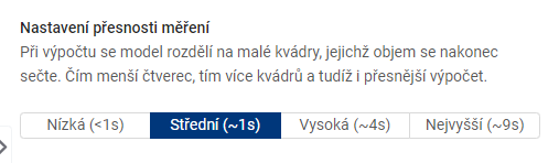
Measurement accuracy setting = the size of the grid used to measure the volume.
-
Real polygon area = polygon area in 3D space.
-
Projected polygon area = the area of a 2D polygon that is the orthogonal projection of a 3D polygon onto a horizontal surface.
-
Real polygon perimeter = the sum of the lengths of all sides of the polygon in 3D space.
-
Projected polygon perimeter = the perimeter of a 2D polygon that is the orthogonal projection of a 3D polygon onto a horizontal surface.
-
Min. altitude = the point with the lowest coordinate value on the Z axis.
-
Max altitude = the point with the highest coordinate value on the Z axis.
-
Difference in altitude = difference between Max. altitude difference between Min. and Min. altitude.
MEASUREMENT SETTINGS
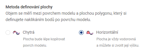
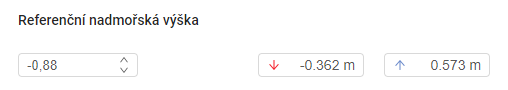
The reference altitude is used to set the height of the plane in the case of measurements by the Horizontal method.
MEASUREMENT VALUES
The table Measurement values shows the calculations for each measurement point.
-
Actual distance = the distance corresponding to the link between this point and the previous point. In the case of the first point, the value 0 is given.
-
Projected distance = the distance corresponding to the length of the horizontal overhang (with angle 0°) in an imaginary triangle, where this point represents the vertex between the overhang and the horizontal overhang. The preceding point then represents the vertex between the hypotenuse and the vertical suspension (with an angle of 90°). In the case of the first point the value 0 is given.